Reasons Why Engineers Rely on CAD for a Good Drainage System

Why do our cities still flood? Have you ever wondered why some areas flood even after new roads and buildings are built?
Why does water still get collected on streets, in parking lots, or around homes, even with ‘modern’ drainage systems?
And most importantly, can better planning really make a difference? Sounds overwhelming? Don’t worry, because CAD Connect has answers to all these questions.
To begin with, flooding isn’t just caused by heavy rain. It’s often the result of poor drainage design, outdated planning, and a lack of visualization before construction begins. A small design mistake can block the natural flow of water and cause major issues later.
This is where Computer-Aided Design steps in, helping engineers, designers, and planners to visualize, simulate, and optimize drainage systems before a single pipe is laid. In this blog, CAD Connect explores how CAD tools are changing the way drainage systems are designed and how they help prevent flooding in both urban and rural areas.
What Makes a Good Drainage System
A good drainage system is like the veins of a city. It carries excess rainwater away from roads, buildings, and open spaces to avoid flooding.
But designing one is not as easy as drawing a few lines and pipes.
A proper drainage design must consider:
- The slope and elevation of the land
- The type of soil and its ability to absorb water
- The size and flow rate of pipes
- Stormwater collection points and outfalls
- Future urban growth
If any one of these factors is ignored, even a short rainfall can lead to waterlogging and damage.
Traditionally, many engineers designed these systems using manual drawings and assumptions. But with growing urban populations and unpredictable rainfall, manual methods can’t keep up. That’s why modern designers rely heavily on CAD software to create accurate and efficient drainage layouts.
How CAD Brings Clarity to Drainage Design
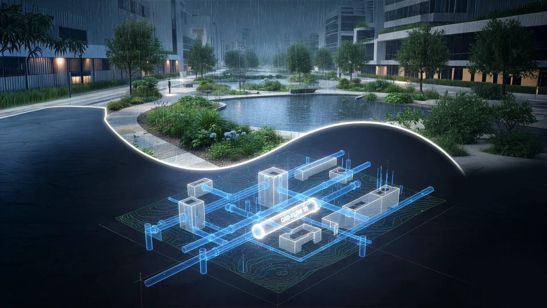
CAD software helps designers build realistic 2D and 3D models of drainage systems. Instead of guessing how water might flow, designers can see it.
Let’s look at how CAD makes the difference:
a. Visualizing the Entire System
Using CAD, a designer can create a full layout of pipes, channels, catch basins, and manholes. Everything can be viewed in both 2D schematics and 3D perspectives, helping teams understand how water will move across the site.
Even before construction starts, teams can check:
- Will rainwater move smoothly toward the main drain?
- Are there any low spots where water might collect?
- Does the slope of the terrain support quick runoff?
These visual insights are impossible to achieve with manual drawings alone.
b. Easy Modifications and Real-time Updates
Every construction site faces last-minute changes, a new road level, a building shift, or a landscape modification.
In traditional drawings, updating these changes is slow and often confusing.
With CAD, any change can be instantly reflected in the entire drainage layout. The system automatically adjusts pipe slopes, lengths, and alignments, saving hours of redrafting time and reducing errors.
c. Integration with Terrain and Survey Data
Modern CAD tools can import survey data and topographical maps directly into the design.
This means the drainage model is built on real-world terrain, not on rough estimates. Designers can simulate rainfall over the actual ground surface and see exactly where water might flow or collect.
This integration is a game-changer for flood-prone zones where even minor elevation differences can cause water pooling.
Seeing the Invisible Flow
One of the biggest strengths of CAD in drainage design is 3D modeling.
Imagine being able to walk through your drainage system virtually, checking every pipe, connection, and slope before a single trench is dug. That’s exactly what 3D CAD allows.
a. Spotting Design Conflicts
3D models make it easy to detect clashes between pipes, utility lines, or foundations.
A drainage pipe running too close to an electrical conduit can cause costly site corrections later. CAD’s clash detection prevents that early on.
b. Simulating Water Flow
Some advanced CAD tools allow flow simulations, showing how water behaves during light rain or heavy storms. Designers can adjust pipe diameters, slopes, or inlets until the flow is perfectly optimized.
c. Communication Made Simple
3D visualizations are not just for engineers, they help clients, contractors, and local authorities understand the plan without technical jargon.
Instead of explaining with drawings, you can show them how the system will prevent flooding, and that builds trust.
Building Smarter, Greener Systems
Flood control isn’t just about moving water away, it’s about managing it wisely.
Modern designs aim to collect and reuse stormwater for irrigation, landscaping, or even groundwater recharge.
With CAD tools, designers can plan:
- Permeable pavements that let water soak into the soil
- Rain gardens and detention ponds for natural absorption
- Green roofs that reduce surface runoff
All these eco-friendly features can be tested and visualized in CAD before construction.
This helps designers create systems that not only prevent floods but also support sustainability.
The Role of CAD in Smart City Planning
As cities grow, managing rainwater is becoming a serious challenge.
Smart cities need intelligent drainage systems that adapt to both climate and population changes.
With CAD:
- Large networks of drains and culverts can be modeled together.
- Engineers can test different rainfall scenarios using real data.
- Authorities can plan maintenance schedules based on visual data.
For example, a city drainage department can use CAD drawings to identify blockage points or plan future expansion.
It’s like giving a city a detailed X-ray of its underground drainage network, helping to prevent disasters before they happen.
Collaboration Made Easy with CAD Platforms
Drainage projects usually involve multiple professionals, civil engineers, architects, contractors, and local authorities.
In traditional workflows, communication gaps often lead to confusion and errors.
With CAD-based collaboration:
- Everyone works on the same digital model
- Changes are automatically updated across all drawings
- Cloud-based tools allow remote review and approval
This smooth coordination keeps projects on time and within budget.
In fact, many companies now use Building Information Modeling (BIM) tools alongside CAD for drainage and stormwater management. It’s all about creating a connected and efficient design ecosystem.
The Future of Drainage Design: From Reactive to Predictive
In the past, drainage systems were built after floods occurred. Now, with CAD and digital modeling, we can predict and prevent flooding.
By combining CAD data with weather models, AI, and GIS systems, designers can:
- Identify risk zones
- Forecast water movement during storms
- Plan emergency water storage areas
This shift from reactive design to predictive planning is what will keep future cities safer.
Designing with Vision, Not Just Pipes
Floods may look like nature’s fury, but many times, they reflect poor design decisions.
The good news? With the power of CAD, we can change that story.
By visualizing every curve, slope, and channel in advance, designers can create drainage systems that work with nature, not against it.
Whether it’s a small community project or a large city network, CAD helps turn ideas into intelligent, flood-free solutions.
So, the next time you see heavy rain, imagine the quiet heroes underground, the drains, pipes, and channels that keep your streets dry, all perfectly designed with CAD precision. And if you want to dig deeper to know how CAD excellence works so perfect, you will have to connect with the CAD experts, CAD Connect.